Loop Antenna Radiation Pattern
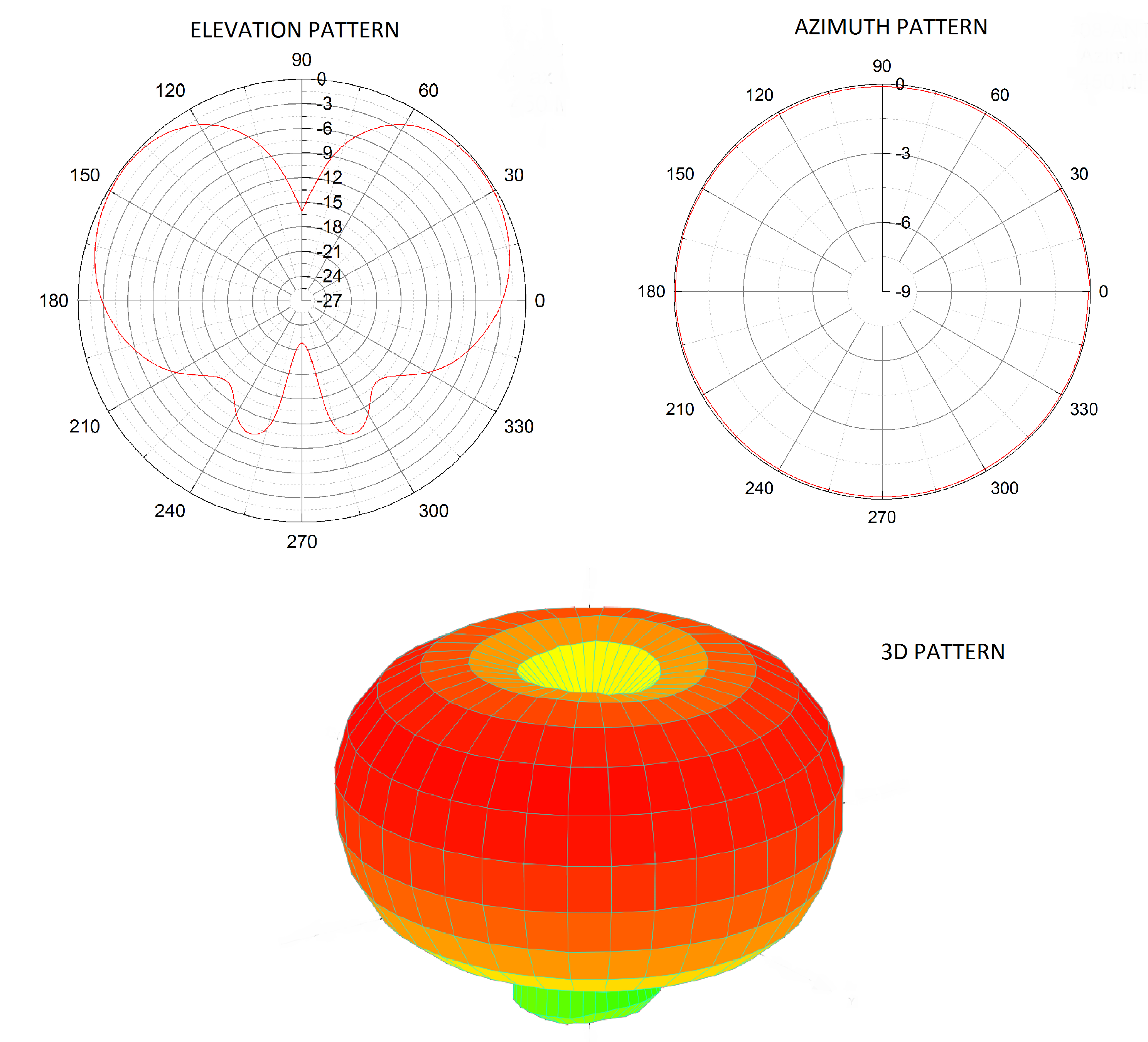
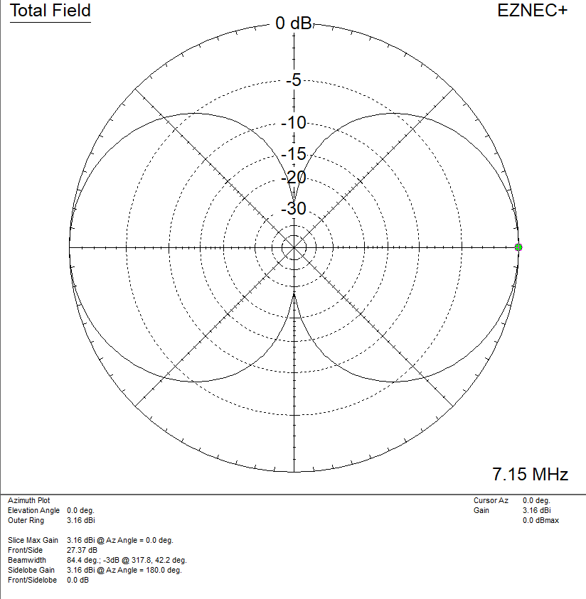
Loop Antenna Radiation Pattern - Web azimuth radiation pattern of a horizontally polarized full wave loop antenna in free space. The tangent line at 0° indicates vertical polarization, whereas the line with 90° indicates horizontal polarization. The radiation patterns for different angles of looping are also illustrated clearly in the figure. Here, c denotes the loop’s circumference. This power variation as a function of the arrival angle is observed in the antenna's far field. This still qualifies as a “small loop”, but is beginning to show some of the characteristics of a larger loop. The radiated power is now maximum along the axis of the loop, not in the plane of the loop. The small loops of a single turn have small radiation resistance (< 1 ω) usually comparable to their loss resistance. The pattern is similar to a dipole, but about 6 degrees wider however, the vertical pattern is more compressed, providing about 1 db of gain. These antennas have low radiation resistance and high inductive reactance, so that their impedance is difficult to match to a radio impedance (often 50 ohms). The pattern is similar to a dipole, but about 6 degrees wider however, the vertical pattern is more compressed, providing about 1 db of gain. Web loop antennas are usually classified as electrically small ( c < λ / 3 ) and electrically large (c ∼ λ ). Radius of loop= 5.3 mm, circumference = λ. Web let’s start with a simple square loop in free space, fed in the middle of one side, and see how the radiation pattern and other characteristics vary as we change the frequency (or change the length in wavelengths, which is the same thing). The small loops of a single turn have small radiation resistance (< 1 ω) usually comparable to their loss resistance. This power variation as a function of the arrival angle is observed in the antenna's far field. Courtesy himanshu rohilla, 3rd year ee, iit delhi. The tangent line at 0° indicates vertical polarization, whereas the line with 90° indicates horizontal polarization. Here, c denotes the loop’s circumference. As the frequency progresses to the second and third resonances the perpendicular radiation fades and strong lobes near the plane of the loop arise. Web an antenna is a device that couples currents to electromagnetic waves for purposes of radiation or reception. Web the antenna feed points would be in series with the loop, such that a small loop looks somewhat like a short circuit across the antenna feed. Courtesy himanshu rohilla, 3rd year ee, iit delhi. Web azimuth radiation pattern of a horizontally. Web let’s start with a simple square loop in free space, fed in the middle of one side, and see how the radiation pattern and other characteristics vary as we change the frequency (or change the length in wavelengths, which is the same thing). This power variation as a function of the arrival angle is observed in the antenna's far. Radius of loop= 5.3 mm, circumference = λ. The small loops of a single turn have small radiation resistance (< 1 ω) usually comparable to their loss resistance. The radiated power is now maximum along the axis of the loop, not in the plane of the loop. These antennas have low radiation resistance and high inductive reactance, so that their. Courtesy himanshu rohilla, 3rd year ee, iit delhi. Web an antenna is a device that couples currents to electromagnetic waves for purposes of radiation or reception. Web the antenna feed points would be in series with the loop, such that a small loop looks somewhat like a short circuit across the antenna feed. The pattern is similar to a dipole,. These antennas have low radiation resistance and high inductive reactance, so that their impedance is difficult to match to a radio impedance (often 50 ohms). Web loop antennas are usually classified as electrically small ( c < λ / 3 ) and electrically large (c ∼ λ ). The small loops of a single turn have small radiation resistance (<. Web let’s start with a simple square loop in free space, fed in the middle of one side, and see how the radiation pattern and other characteristics vary as we change the frequency (or change the length in wavelengths, which is the same thing). The pattern is similar to a dipole, but about 6 degrees wider however, the vertical pattern. This power variation as a function of the arrival angle is observed in the antenna's far field. This still qualifies as a “small loop”, but is beginning to show some of the characteristics of a larger loop. The small loops of a single turn have small radiation resistance (< 1 ω) usually comparable to their loss resistance. These antennas have. As the frequency progresses to the second and third resonances the perpendicular radiation fades and strong lobes near the plane of the loop arise. The tangent line at 0° indicates vertical polarization, whereas the line with 90° indicates horizontal polarization. Web the antenna feed points would be in series with the loop, such that a small loop looks somewhat like. Courtesy himanshu rohilla, 3rd year ee, iit delhi. This still qualifies as a “small loop”, but is beginning to show some of the characteristics of a larger loop. As the frequency progresses to the second and third resonances the perpendicular radiation fades and strong lobes near the plane of the loop arise. Web loop antennas are usually classified as electrically. Here, c denotes the loop’s circumference. The radiation patterns for different angles of looping are also illustrated clearly in the figure. The radiated power is now maximum along the axis of the loop, not in the plane of the loop. Web let’s start with a simple square loop in free space, fed in the middle of one side, and see. The radiated power is now maximum along the axis of the loop, not in the plane of the loop. The small loops of a single turn have small radiation resistance (< 1 ω) usually comparable to their loss resistance. Web an antenna is a device that couples currents to electromagnetic waves for purposes of radiation or reception. The tangent line at 0° indicates vertical polarization, whereas the line with 90° indicates horizontal polarization. Courtesy himanshu rohilla, 3rd year ee, iit delhi. This still qualifies as a “small loop”, but is beginning to show some of the characteristics of a larger loop. Web azimuth radiation pattern of a horizontally polarized full wave loop antenna in free space. These antennas have low radiation resistance and high inductive reactance, so that their impedance is difficult to match to a radio impedance (often 50 ohms). This power variation as a function of the arrival angle is observed in the antenna's far field. Web a radiation pattern defines the variation of the power radiated by an antenna as a function of the direction away from the antenna. Web loop antennas are usually classified as electrically small ( c < λ / 3 ) and electrically large (c ∼ λ ). The pattern is similar to a dipole, but about 6 degrees wider however, the vertical pattern is more compressed, providing about 1 db of gain. Web let’s start with a simple square loop in free space, fed in the middle of one side, and see how the radiation pattern and other characteristics vary as we change the frequency (or change the length in wavelengths, which is the same thing). The radiation patterns for different angles of looping are also illustrated clearly in the figure.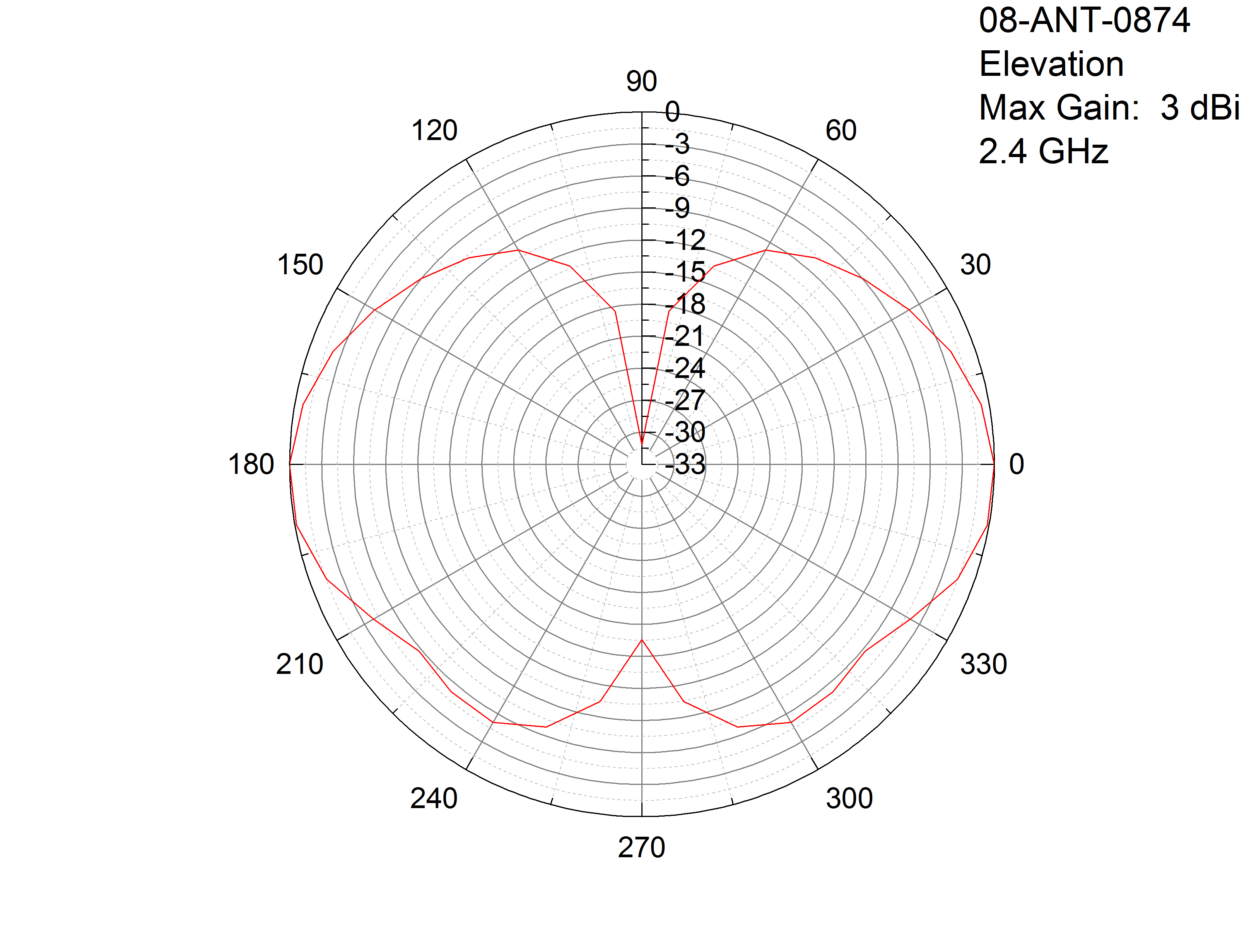
Antenna Gain and radiation patterns explained by MP Antenna

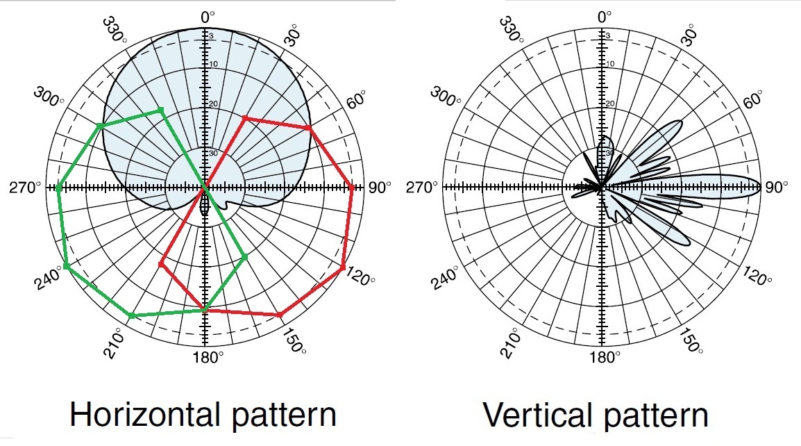
Simulated radiation patterns of the reference rectangular loop antenna
RadiationPatternLoopAntenna IoT M2M blog
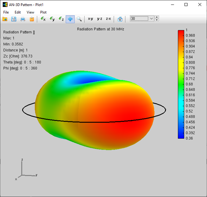
Loop Antenna › ANSOF Antenna Simulation Software
Omnidirectional Antenna Radiation Pattern
Theory of Full Wave Loops Practical Antennas
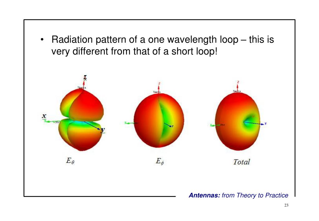
PPT Antennas from Theory to Practice 5. Popular Antennas PowerPoint
Antenna Radiation Pattern and Antenna Tilt RAYmaps

Loop Antenna Radiation Pattern Catalog of Patterns

Radiation pattern plot of the loop antenna. Download
As The Frequency Progresses To The Second And Third Resonances The Perpendicular Radiation Fades And Strong Lobes Near The Plane Of The Loop Arise.
Web The Antenna Feed Points Would Be In Series With The Loop, Such That A Small Loop Looks Somewhat Like A Short Circuit Across The Antenna Feed.
Radius Of Loop= 5.3 Mm, Circumference = Λ.
Here, C Denotes The Loop’s Circumference.
Related Post: